
I actually hadn’t been planning to build this until later, but on the first of May (2018, for the record) I got bored and figured since I had the parts, why not? I vastly underestimated the amount of time it would take, figuring I would be done before lunch and ending up taking all day. It was… interesting, to say the least.
Dallas Mod
I did cheat a little and did some prep work off camera. This board uses a Dallas real-time clock module, which contains the battery inside a sealed package. Of course, over 20 years later it was totally dead. I had replacement clock modules on the way but got impatient and ended up hacking up the original instead.
I used a small (“junior”) hacksaw to cut into the clock module, which worked well. The existing battery was dead as a doornail, reading 0.04V. I cut clean through one lead to isolate it- it doesn’t seem to be strictly necessary and many modders don’t do it but I feel better with the old battery out of the circuit.
I didn’t have a coin cell holder and didn’t have a fast, cheap way of getting one, so I improvised. I bought a pack of LED tealights at a dollar store. These are the cheapest things going, consisting of an LED and lithium coin cell in junky white plastic. They’re cost-downed as far as cost-downing can get, with the leads of the LED forming the battery contacts and the “switch” just pushing one lead around.
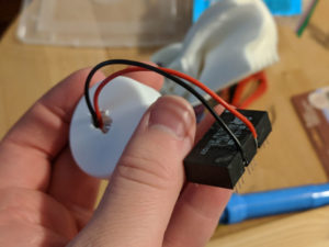
I cut off the top of the LED and soldered some wires on, routing them through the hole in the top where the “flame” would be (which I ended up having to enlarge anyway). It looks stupid, and maybe it is, but it works. I choose to see it as a point of uniqueness. I could use a new Dallas RTC, one with a coin cell holder, or a new drop-in replacement, but those are so been-there done-that. This is probably the only PC in the world where the clock is maintained by a tealight.
Pretesting Processors
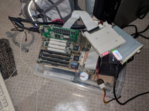
After getting the real-time clock module wired up, I threw it in the motherboard and tested the whole setup. It booted fine and maintained time with the new module, though it seems this system is not Y2K compliant. I installed DOS on the disk on module, and tried out my Gotek floppy emulator for the first time. This thing is slick, and I can see why it’s so widely recommended. I was able to run cachechk and speedsys without having to fire up my XP machine to write floppies.
I used the Pentium 133 for initial testing because I knew it was a supported combination, and it ran just fine. However, when I swapped out for the Pentium 233 MMX, things were not so rosy. No matter what I tried, it would only run at 133MHz or 166MHz. To be clear, this motherboard probably doesn’t support this processor, and it’s running it overvolted, but I figured the processor should run at 233MHz and fail in some way, not simply refuse to run at the proper speed.
The explanation behind this is a little bit complicated. The processor frequency should be 233 MHz, which is 3.5 times the bus frequency of 66 MHz. This motherboard can’t set a 3.5x multiplier directly- in fact, no Socket 7 motherboard can, since there are only two physical multiplier lines. Yes, there are actual pins on the processor set high or low to set the clock multiplier. The available multipliers are 1.5x, 2.0x, 2.5x, and 3.0x. Super Socket 7 (and maybe later AMD-targeted Socket 7 motherboards) have an additional line to set higher multipliers, but Intel (and I think Centaur and Cyrix) used a different trick here. On a 233MHz Pentium MMX, the 1.5x multiplier is interpreted as 3.5x. So we need to set the jumpers for a Pentium 100…
Which gets us 133MHz, or 2.0x66MHz. What? Clearly something is wrong here. One would expect the internal magic multiplier to either work and give us 233MHz, or fail and give us 100MHz. In fact, we can only actually get two real multipliers with this motherboard/processor combo. Either 2.0x for 133MHz, or 2.5x for 166MHz. That makes no sense- we should be able to get 100MHz/233MHz (1.5x/3.5x), 133MHz (2.0x), 166MHz(2.5x), or 200MHz(3.0x). But if you look at what the actual multiplier lines are…
| Mult | BF0 | BF1 |
| 1.5x | 1 | 1 |
| 2.0x | 0 | 1 |
| 2.5x | 0 | 0 |
| 3.0x | 1 | 0 |
It looks like BF0 isn’t doing anything at all, and only BF1 is actually affecting our Pentium MMX! In fact, this is not from the truth. Digging through the datasheets we find one interesting change between the classic Pentium and the Pentium MMX. On the classic Pentium, both lines are pulled up (giving a default 1.5x multiplier), while on a Pentium MMX, BF0 is pulled down and BF1 is pulled up (giving a default 2.0x multiplier).
The clock multiplier jumpers on this motherboard are two-pin, and I suspect directly pull down the multiplier lines when closed. This relies on the internal pull-up inside the processor, and would have worked fine with the classic Pentium where both are pulled high internally. However, because BF0 is pulled low inside the MMX, it’s effectively useless, and we can only select the 2.0x or 2.5x multipliers using the still-working BF1 line.
It’s disappointing that I can’t use the 233MHz MMX, and at first felt like a classic Intel anti-consumer move. However, boards like mine really aren’t meant to support the Pentium MMX, lacking split rail voltage, so maybe this was a deliberate and a smart move to prevent problems with incompatible hardware. And while it would be something that is possible to “fix”, I don’t plan on trying it.
Final Parts List
You can view the original parts list in the first part of this series. I’ve made a few changes and corrections since then:
Case: Salvaged AT Tower
I have no idea who made this case or even what it’s model number is. It has a “Kicks” case badge but that’s almost certainly the local computer store that put it together, not the maker of the case itself. There’s nothing special about this case- it’s beige, takes an AT motherboard, has some spots for drives, and has a row of buttons and lights on the front. It has one (mostly unusable) 80mm fan mount. I’ve seen this particular case used in other builds, and my dad might have had the same one with his 486. It’s the right shape, size, and era, and in pretty good condition, so it’ll do.
Possible Processor Upgrade: Pentium Overdrive MMX 200
The Pentium MMX 233 won’t work at full speed because of the aforementioned multiplier issues, and it’s probably iffy running overvolted especially with the wimpy VRM on this motherboard. I’ve already stated that something like a K6 or WinChip is not an option, though the adapters designed for some of those processors would also work with the Pentium MMX. I could go with a classic Pentium at 200MHz, but my preference is the Pentium Overdrive MMX 200. The Overdrive processors are very cool in my eyes, but unfortunately kind of rare and expensive.
Optical Drive: LiteOn DVD-RW Drive
I was wrong about the brand of the optical drive and when it was made. It’s actually a LiteOn from 2003, not an LG from 2009. I did have an LG at one point and that was probably the drive I was thinking of, but this is a completely different one. It does pretty much the same thing.
Floppy Drive: (Different) Generic 3.5″ 1.44MB
The floppy drive I was originally going to use didn’t work. I don’t think it’s broken, since it worked in the machine I pulled it from, but it might be misconfigured (it has some jumpers on it) or not like the cable or controller I was using. Instead I’ll be using a very similar one pulled from the 486, which does work.
Power Supply: Corsair CX450
The XFX 650W power supply didn’t fit in the case. I could sort of squeeze the power supply in but that left the cables where the optical drive needed to be. The CX450 from Corsair (built by Channel Well Technology) is a modern DC-DC design with 80 Plus Bronze certification and a 120mm fan. Most importantly, it’s a lot shorter than the XFX unit! I actually wanted the modular version (CX450M), but this one was on sale for an excellent price.
Mouse: Microsoft Intellimouse w/IntelliEye 1.0
This mouse was a lucky find at the thrift store. It didn’t clean up nicely- the dirt came off and so did the (pretty neat) markings. This is an optical mouse with a scroll wheel that supports USB and PS/2, and has the classic curved design. It would have been a very nice mouse circa 2000, and though it’s a little new it works well with the build.
Building Like It’s 1995
I won’t go through the whole build process here- the video does a much better job of explaining it. Instead I’ll go over some of the specific challenges I ran into and my overall opinion of the build process.
Getting the motherboard in was frustrating. This case uses weird plastic standoffs with notches, so you drop the motherboard in and then slide upward to lock. I really don’t understand the point of this. Screwing in standoffs is actually easier in practice (because the board never goes in flat), and far more secure. In fact, there are two brass standoffs in the case anyway to lock it in place! Also, it seems that the AT formfactor isn’t entirely standardized, because there were no holes that lined up to the leftmost column on my motherboard.
Complaining about IO shields is practically a rite of passage these days, but they’re better than the alternative. Punching out knockouts in the case is kind of fun, but I was worried I was going to break something by bashing them. Presumably you’re supposed to do this first, before installing anything. It also leaves the issue of connectors that didn’t exist when the case was designed- like the PS/2 mouse port. I used a slot bracket for this, which works, but if you can’t get any ports into the case you’re going to run out of slots quick. Having a generic rectangular opening and leaving the specifics up to the motherboard vendor really was a stroke of genius.
I would also appreciate if the connectors were properly keyed, and properly standardized. Floppy and disk drive (IDE) were standardized by this time, but serial and parallel headers were only “mostly the same” and I had to modify the PS/2 mouse bracket specifically for this motherboard. Some colour coding would both make things easier to get into the right spot, and make the motherboard look nicer. It all sounds like petty nitpicking, but getting the connectors into the right spot and in the right way is quite a challenge in the tight, dark confines of a partially build computer.
I’m just not sure what the hell they were thinking with the removable drive cage. You can’t put the cage in and then put the drives in, because the motherboard tray blocks access to the screws. However, it’s almost impossible to get things lined up well enough to get it back in with the drives installed, and trying to get the cage in and out with cables in the way is a nightmare.
Cable management was an exercise in futility. Most of the cables are barely long enough, leaving little slack to route them around. There’s no space behind the motherboard tray, and very little between the power supply and 5.25″ bays. Some of the cables I was worried about bending too much, because it’s possible to break them this way. I did the best I could, but I’m not happy with the result
In fact, in general, the design of this case is terrible. It has no cooling for the hard drive, and in fact only one 80mm fan mount, which won’t take a normal thickness fan. The front panel stuff is mounted to the bezel itself and the wiring is an unlabeled rats nest. The case is not deep enough to have a decent amount of clearance between the optical drives and the power supply. It’s not wide enough for cable management. The removable drive cage is full of fail. There’s four inches of dead space above the motherboard. There’s no toolless anything. Maybe it’s unfair to judge a 1993 case by 2018 standards, but there are no technical or financial limitations here. Everything I described could have been done with 1993 technology, and would not have added significant cost. I guess these things just hadn’t occurred to anyone.
PC building has definitely changed over the years, and definitely for the better. Even a cheap case is easy to build in- I was pleasantly surprised by this a few years back. There are far fewer connectors to plug in, and most of them only go in one way. Cooling is better, cable management is better, and there’s a lot less room for human error. There are also usually fewer components- you might have one or two hard drives and a video card, not a plethora of drives and three or more expansion cards.
This was the most frustrating build I’ve done, maybe even including some of the mods and theme builds. On the other hand, it’s also one of the most fun, because it was so different from what I’m used to. Yeah, it sucked, but it was also awesome. It’s hard to put into words, but I’d definitely rate this as a positive experience overall.
The Next Step
This is far from the end of the The Lazarus Project. Building the PC and documenting it was only one goal among many- there’s still the whole world of actually using it to explore! I installed Windows, did some testing, and even played some games after building the PC but didn’t capture it on camera because I was just too tired. That will be documented in some form, probably with a kind of tour of the system. I’ll be trying various games from the era, of course, mostly my own childhood favourites but some I’ve never played as well.
Acknowledgements
Terry Stewart (Tezza) for a guide on modding the Dallas RTC
Peter H. Wendt/pw-software production for another Dallas RTC mod guide
Chris Hare/PC Hardware Links for the one source of information I could find on why my clockspeed was wrong
The Intel Pentium and Pentium MMX datasheets for more information on BF0 and BF1 (not available from Intel anymore but there are mirrors online)
omfgdude and DST for the background music in the video (all licensed CC0, but included for politeness)