
The motherboard mounting on the door is by far the most complex part of the conversion. Fortunately, the Laserhive conversion kit takes care of most of the work. It’s pretty straightforward to remove the old and install the new, but there are a few things I ran into.
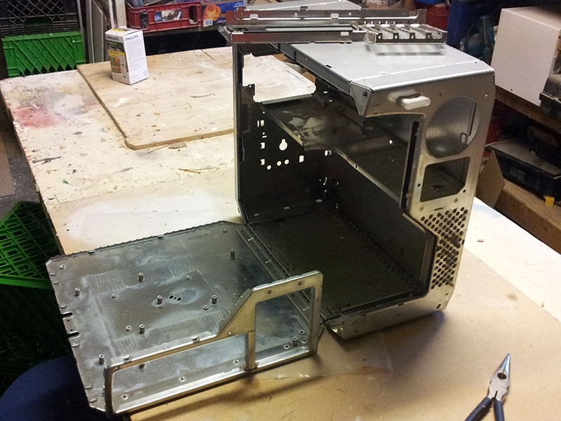
The original back panel has to be modified first. The inner part that used to hold the expansion cards and I/O shield is riveted in. Drilling out rivets is easy, but annoying. Next, the post in the middle of the back has to be cut out. The far right portion of the new I/O shield would be covered up if this wasn’t done. I used a small hacksaw and cleaned up the edges with a sanding drum on a Dremel.
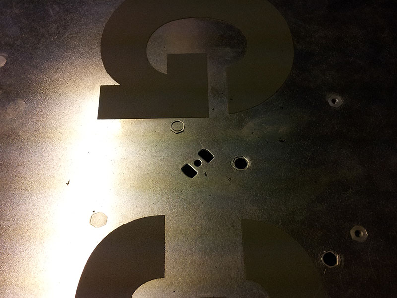
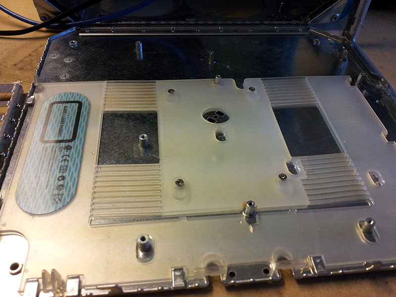
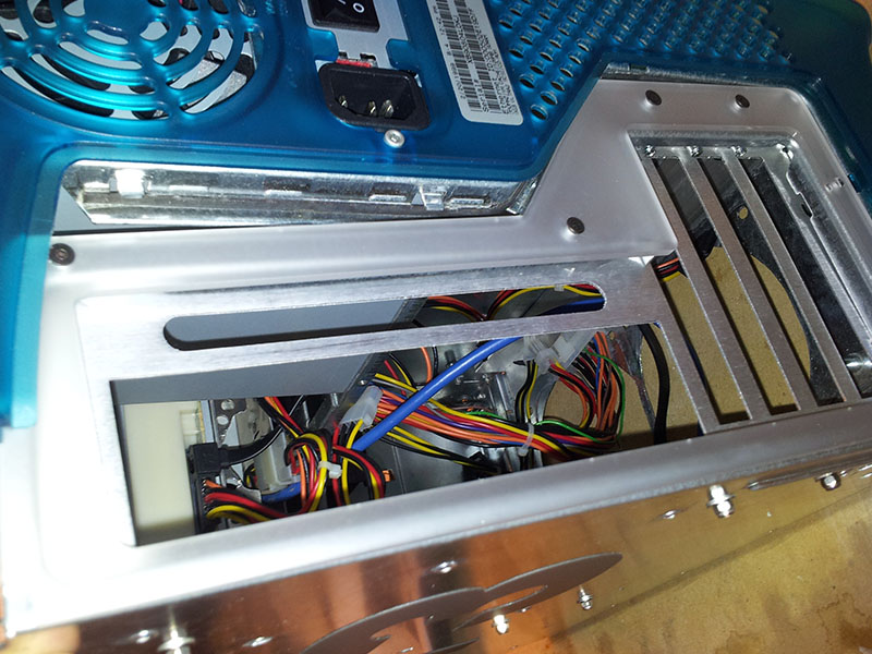
Some of the original motherboard mounting posts interfere with the installation of the motherboard. The kit instructions recommend snapping them out with pliers or cutting them down with a Dremel, with the latter preferred because it won’t distort the case. However, there’s a better option, which is to just drill the posts out from the back side. Center punch, small bit, big bit. Once most of the material is removed, the remaining bits of post just snap off. It’s quick and clean, although it does leave holes. We later covered them up with foil tape, but in all honesty you won’t really notice the holes once the machine is assembled.
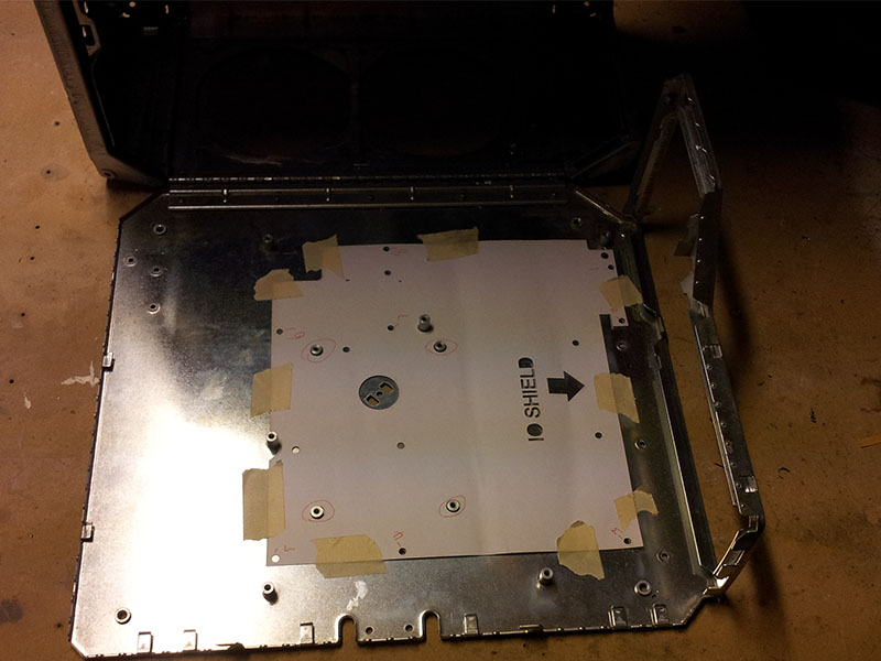
This template is well designed and worked well once I figured out which way it went, but it’s not perfect. It’s missing cutouts for a few posts, so I had to remove them before I could even get the template on. I think some of the marked holes were wrong for my motherboard. I’m wondering if there were some changes between the G3 and G4 that weren’t well documented until now.
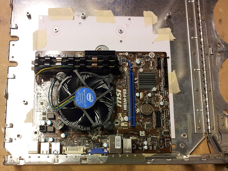
Once the template was in place, I drilled out the holes I needed and didn’t bother with the ones I wouldn’t. There are holes for a full-size microATX board, but the one I’m using is much smaller and doesn’t use many of the holes. The instructions specify a 3-4mm bit, so I used an 1/8″ bit which is very common and falls right between the recommended sizes.
The plastic latch had to be modified with new slots to clear the new standoffs. Some don’t even bother with this piece, but I really wanted to have the original latch and it turned out to be trivially easy to do anyway. I burned my way through the plastic with a Dremel grinding bit. A heated knife works but the Dremel is much faster. This is fairly brittle plastic, so I wouldn’t recommend anything that could crack it. Even though I was careful, there are several small cracks already. The flat mounting screws are a nice little detail from the Laserhive kit.
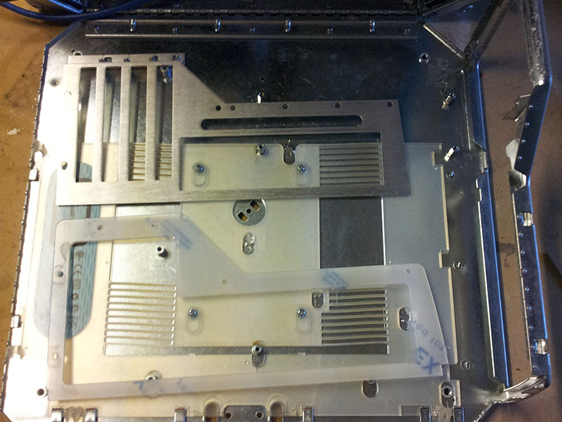
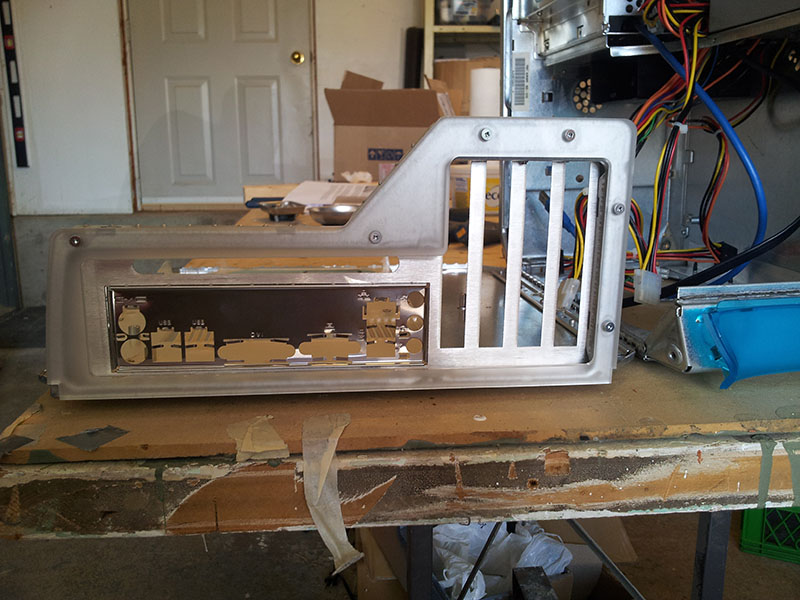
The Laserhive kit includes two back pieces. The aluminum piece goes on the inside of the original back panel and holds the I/O shield and expansion cards. The plastic piece goes on the outside and provides a clean finish. The standard colour is grey but I paid a little extra for a translucent white one which matches the white parts of the case fairly well. There was no hope of getting one to match the blue colour of the original, although now the Laserhive site seems to be advertising such a part.
I don’t meant to discount this kit- it’s still by far the most elegant option- but out of the box, it didn’t actually fit. It’s literally a square peg in a round hole situation- the edges of the back piece are rounded and the aluminum piece is squared. I’m wondering if this is another subtle G3 versus (late?) G4 difference.
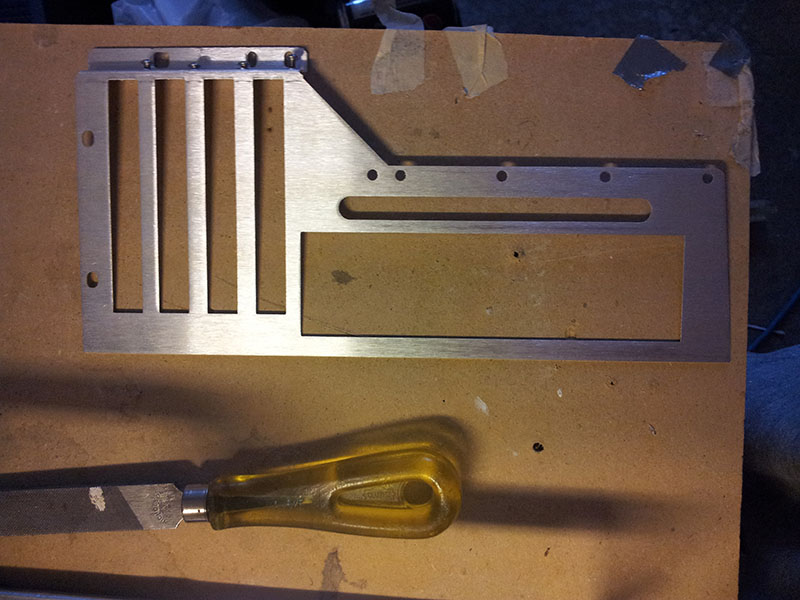
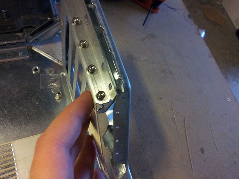
A bit of filing took care of the problem. Also note the hex head machine screws that go into inserts to hold in expansion cards. It’s much better than simply drilling holes through the aluminum and hoping that the threads will hold, although I dislike the nonstandard hex head screws.
Test-fitting requires installing the rear plastic panel. Fortunately, that’s the first piece that needs to go on. I think I also installed the power supply at this point because the mounting bolts help hold the rear panel in. The new rear panel bolts in with neat black oxide flat head screws and brass mushroom nuts. Be careful with tightening these- the aluminum piece is not supported in all the place you’d expect it to be. I trimmed the plastic part slightly to clear the top bolt because of a perceived clearance issue which turned out to be unrelated to the plastic.
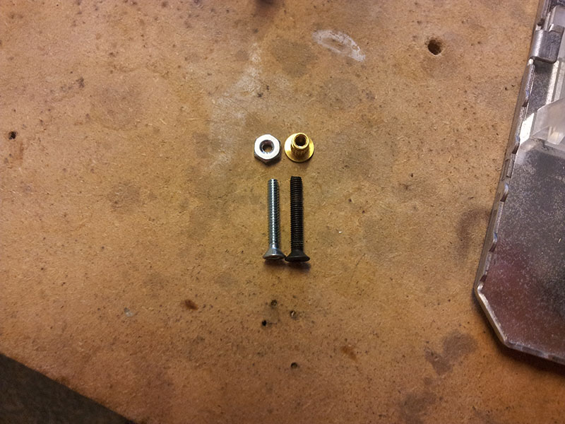
Unfortunately, instead of two short bolts and four long bolts, the kit came with two short bolts, three long bolts, and one medium-length button-head bolt. I’m assuming this was a mistake, and I could probably have asked for replacement hardware, but we wanted to get this done quickly. Trying to find M3 fasteners locally was an exercise in frustration, but 4-40×3/4 machine screws work fine. Two were trimmed to match the short bolts. I bought washers as well, but they didn’t fit and caused the door to bind so I ended up not using them. I figure that since the diameter of the 4-40 nut is about the same as the original mushroom nut, it should be fine.
With the rear panel mounted, motherboard standoffs mounted, and all clearance issues solved, the case was now ready for assembly.